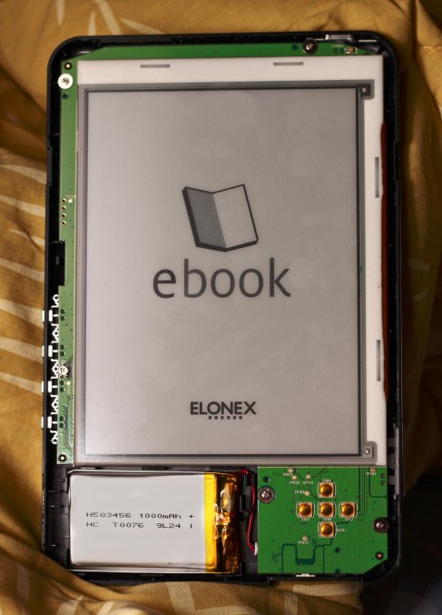
I bought Elonex 621EB ebook reader few weeks ago and I fell in love with e-paper display. According to the package, the firmware is linux based. Having a mobile device with e-paper display and linux sounds like fun, doesn’t it?
I had some problems while reading pdf files and some ebooks (I think they were .epub files) from the internal memory. Almost every time I tried to change the page, whole device froze for 30-60 seconds. I started to realize why this device was on sale for <50€ (usually these exact readers cost around 100-150€). Fortunately I didn’t give up; When using SD-card, turning the page happens in ~2s.
After couple of nights of using the ebook reader to actually read ebooks, I thought “What else this device can do?”. Ok, it has sudoku and mp3-player. Buttons of this reader are not good for playing sudoku and screen refresh rate doesn’t make playing any more pleasant. I didn’t even try the mp3-player. No matter how good the sound quality is, it won’t compensate for the large form factor of the ebook reader. That’s just my opinion, though.
I took small knife and pried the case open. Like expected, most of the components are in the back side of the PCB. There is one small trimmer in the left side of the PCB, next to the side buttons. Don’t know what that does… Then there is a place for 1×4 pin header, left side of the display. That might be UART (Vcc, TX, RX, Gnd)? Lets see if we know more after turning the PCB around.
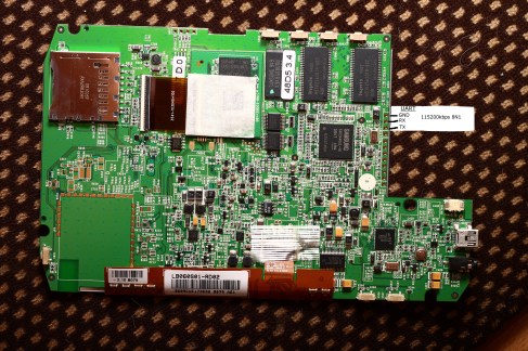
After I found the screwdriver I unscrewed those four small screws and turned the PCB around. It was time to draw a block diagram in my mind: “That area contains RAM, internal flash and the processor, that must be display driver, WiFi would go there on other models… audio stuff goes there” etc. I knew there is another model with WiFi and bluetooth (and maybe some other HW goodies which this model doesn’t have), so it was easy to imagine some components to those empty spots.
There is a daughter board with memory chip and some kind of IC in it, top-center in the picture below. Quick testing revealed that the daugter board contains VRAM like suspected. Below the daughter board’s ribbon cable there is LM75 temperature sensor… Therefore there is I2C-bus’ SDA and SCL easily accessible.
It was time to take Bus Pirate and start looking for serial port. Luckily this reader sends boot messages to the serial port and that way I was able to find the right pins, which are marked in the picture below. Like you can see in the picture, serial terminal uses 115200kbps baud rate, 8 data bits, no parity bit and one stop bit. I browsed through the boot messages and found out that this reader uses U-Boot bootloader and the default user for serial terminal is root. I dumped the files from internal memory to memory card. First thing I tried was modifying strings.list file, which contains strings printed on the screen, for example icon labels. I translated main menu to other language and it worked. Ok, so far everything has worked like a charm.
Back to the HW. I wanted to access the serial port even when the case is closed. Instead of cutting a hole to the case I reused the headphone jack. I desoldered eight parts near the headphone jack: C407, C408, C430, C431, R404, R405, R406 and R407. Removing those parts disconnected tip and ring of the headphone connector from the circuit. They made a band-pass filter which blocked DC and high frequencies from going to the headphones. Then i soldered wires from UART-pins to the headphone jack and closed the case. Now I can use cable with a 2.5mm plug in one end to connect this reader to bus pirate or any other TTL-level serial port.


